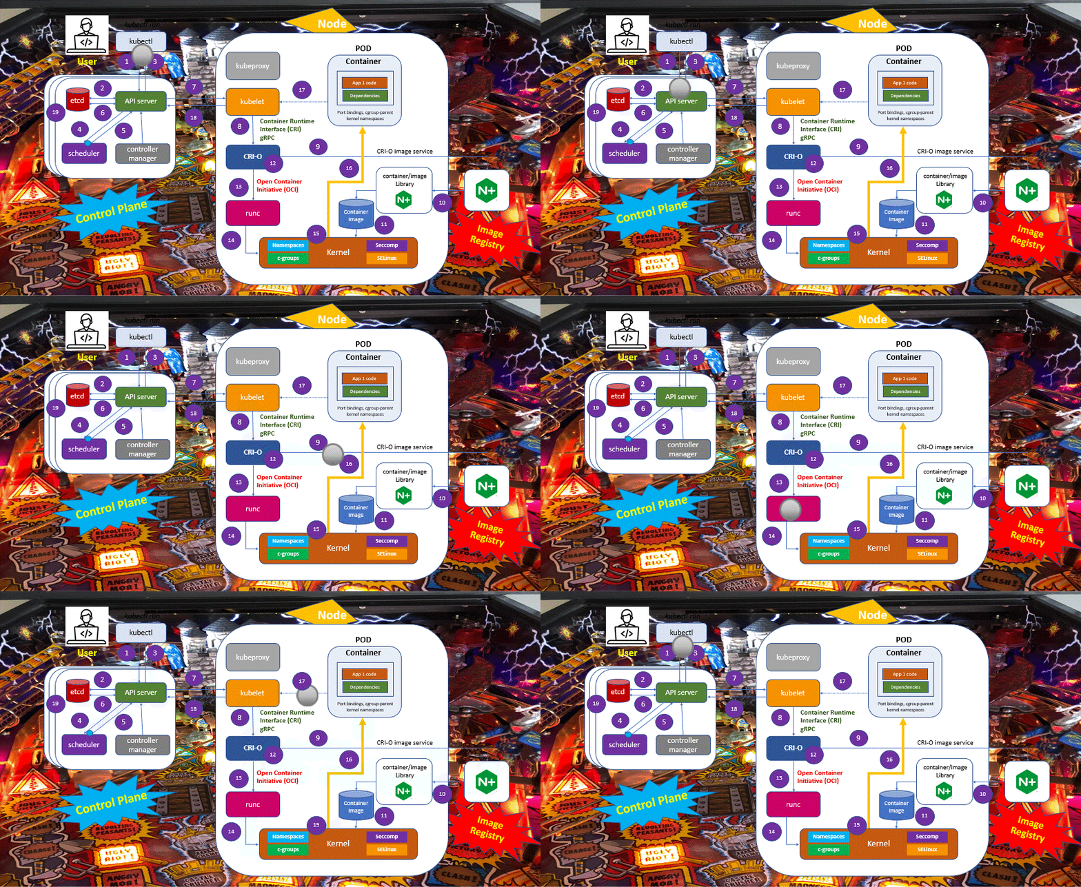
What happens when the Kubernetes API requests a POD creation? In this post, I highlight the components and tasks involved in this process, summarizing their functions and actions.
First off all, let’s remember some basic concepts about Kubernetes.
A Kubernetes cluster consists of worker machines called nodes that run our containerized applications. Every Kubernetes cluster has at least one worker node. But a cluster usually runs multiple nodes, providing fault tolerance and high availability.
Kubernetes nodes host the PODs. A POD is a group of one or more connected containers. And those containers share resources like storage, networking, and a specification of how they should run. So, in a generic analogy, a POD is an element that performs the function of a “logical host”.
We know that the Kubernetes control plane manages the nodes and PODs in the cluster. And we also know that in production environments, the control plane usually runs on at least three nodes to ensure high availability.
The core of the Kubernetes control plane component is the API server.
This server exposes an HTTP API that allows users, using a command-line tool called kubectl, to perform various container management and orchestration tasks, such as: creating, updating, modifying, or deleting a resource, deploying applications, performing updates, and accessing logs.
In addition to the command line interface, you can use GUI dashboards from Kubernetes Orchestrators tools. And it is also possible to access the APIs directly through REST calls from an application, for example.
Creating a POD involves several steps. Everything starts on the control plane.
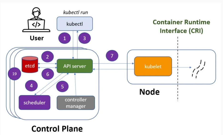
1 – Using the kubectl and performing the “kubectl run” command, a user requests the API server to create a new POD in the cluster. The first operation is the API server authenticates and validates the user credentials.
2 – The API server writes the configuration to the etcd, a distributed key-value data store. It is the source of trust for the cluster and ensures that its state remains consistent.
The etcd confirms to the API server that it has made a successful write for this request.
3 – The API server returns to the kubectl that the POD was created! This fast answer is possible because the etcd already defined a desired state of the cluster. From now, the Kubernetes components will work together to make this desired state equal to the actual state of the cluster.
So, until now, we have the new POD recorded in the desired state for this cluster.
4 – The scheduler keeps an eye on the workloads that need to be created. It also determines which node will place a workload. What it is doing, in a nutshell, is pinging the API server at regular intervals and checking if any workloads need to be scheduled.
At this moment, the API server informs that a new POD needs to get created in one of the nodes. The scheduler looks at the available nodes. It will rule out any unsatisfactory nodes due to resource limitations.
Finally, the scheduler chooses the best node to run the workload by considering all the factors.
5 – Once the scheduler chooses a node, it sends the information to the API server where the POD creation must be performed.
6 – The API server updates the desired configuration in the etcd. After the successful write in the etcd, there is information about the desired state versus the actual state. With this information, the API server knows what it needs to do to make the actual state meet the desired state.
The etcd confirms to the API server that it has made a successful write for this request.
7 – The API server then sends API instructions to a node component called the kubelet.
The kubelet is an agent that runs on each Kubernetes node and is responsible for functions like registering the node with the cluster and sending periodic health checks to the API server. It also creates and destroys workloads as directed by the API server. As a security function, Kubernetes supports SSH tunnels to secure the control plane for node communication paths.
So, abstracting the details of these APIs calls, the API server sends an API message to the kubelet like this: create this POD using node x.
Breakpoint: CRI and OCI
At this point, we have a community-defined communication layer called the Kubernetes Container Runtime Interface, or CRI.
Since the beginning of container technology, several types of runtime containers have been created.
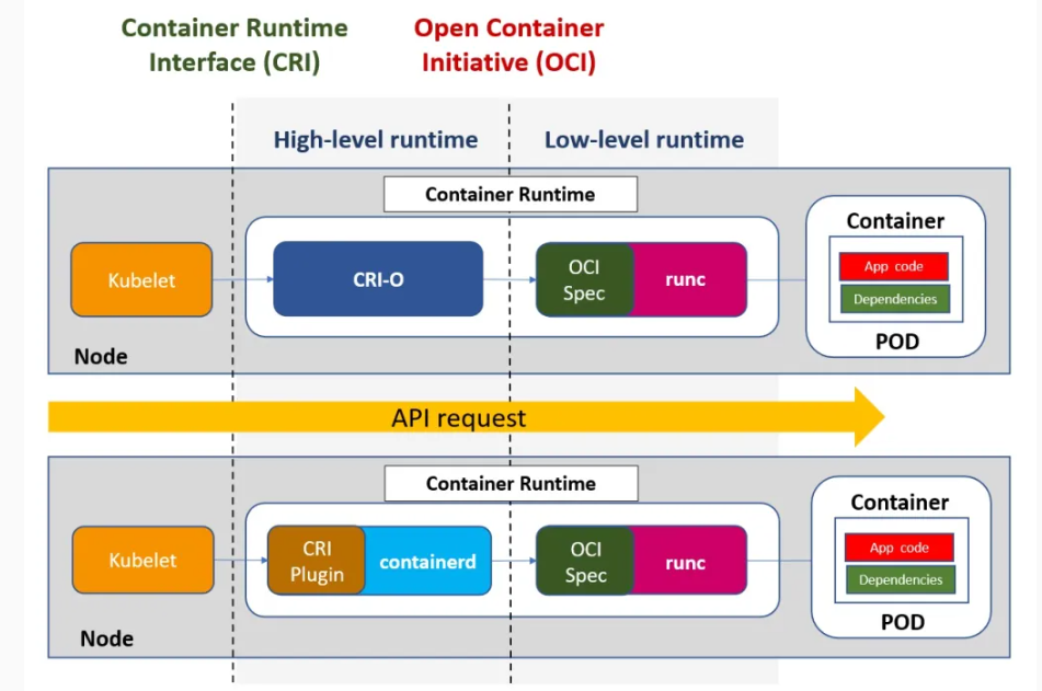
So, CRI defines gRPC APIs that allow the kubelet to interact with various runtime containers without recompiling the cluster components. CRI makes it possible to perform an abstraction for different types of runtime containers, such as Docker, containerd, or CRI-O.
On the other hand, we know that container runtime is the software component responsible for managing the lifecycle of the containers.
It is in charge of defining and creating the isolated environments in which the containers are executed, providing the necessary resources and interfaces for the functioning of the containers, and interacting directly with the functions of the Linux Kernel.
And the OCI Runtime Specification is one of the thee specifications defined by the Open Container Initiative (OCI). It describes the requirements for the runtime environment, the interfaces for containers, and the minimum set of functionalities that container runtimes must provide to be considered OCI compliant.
This specification allows for the creation and management of containers using a standard set of tools and APIs, regardless of the underlying platform. OCI enables interoperability and portability between Docker and Kubernetes, for example.
The OCI Runtime Specification defines a minimum of five standard operations: create, start, state, delete and kill.
It is possible to highlight CRI-O, containerd, and runc as examples of OCI-compatible runtimes and some of the most popular runtimes on the market.
Container runtimes are divided into three main categories:
- High-Level container runtimes like CRI-O and containerd.
- Low-Level container runtimes like runc and crun.
- Sandboxed and virtual container runtimes like gVisor, Firecracker, runV, and kata-containers.
In this example, we are using CRI-O and runc runtimes.
About CRI-O
CRI-O implements the Kubernetes Container Runtime Interface (CRI) and enables Open Container Initiative (OCI) compatible runtimes.
It is a graduated project of the Cloud Native Computing Foundation (CNCF) and is maintained by Red Hat, Intel, Suse, Hyper, and IBM. It is a lightweight alternative to using Docker as a runtime. CRI-O is the default runtime for Red Hat OpenShift and Suse Rancher.
CRIO-O allows running containers in read-only mode. Thus, an attack surface is removed, blocking the actions of intruders in addition to preventing data loss.
The container bundle
There are two most essential components for the creation of a container:
- config.json file.
- container root directory.
The config.json file has the complete layout for the container lifecycle, from container start to deletion. It holds all the metadata for creating the container, like the OCI version, the path for the container root directory, the namespace, resource limit definitions for the container process, user-defined processes, and others metadata.
The container root directory is the topmost directory of a container file system. It is the starting point for a file system tree, which contains all other directories and files in the container.
Back to the POD creation flow
Next steps for creating the POD:
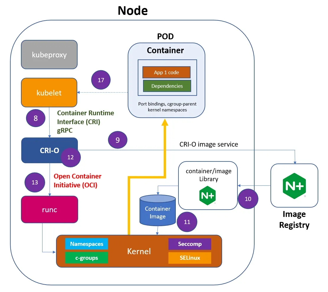
8 – The kubelet forwards the request to the CRI-O using the CRI gRPC interface.
9 – The container root file directory is created.
10 – CRI-O uses the containers/image library to pull the image from a container registry.
11 – The downloaded image is unpacked into the container root filesystem and stored in the containers/storage library. The container image is created.
12 – CRI-O then generates the container OCI runtime specification, a config.json.
13 – CRI-O then launches the runc runtime to start the container creation process.
About runc
The runc container runtime serves as the low-level container runtime and has become a de facto standard in the market.
It is a lightweight and portable implementation of the Open Container Initiative (OCI) container runtime specification. It is also Cloud Native Computing Foundation (CNCF) compliant.
It is implemented using the Go programming language and shares a lot of low-level code with Docker. It provides full support for Linux security features such as Namespaces, SELinux, c-groups, Seccomp, live migration, portable profiles, native DPDK support, and other functions
The features of the Linux kernel:
In Linux, every process has a unique identifier represented by, called the process ID (PID).
A container is just a Linux process. More precisely, it is a forked or cloned process with a dedicated PID.
A container is also an isolated process.
To isolate a container from the other processes, Linux uses some of its native Kernel features.
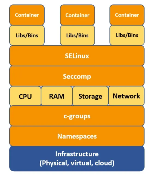
In Linux, a Namespace isolates specific system resources that are generally visible to all processes. Within a Namespace, only processes that are members of that namespace can see those resources.
Another Linux function associated with containers is c-groups (Control Groups). It is a Linux kernel feature that limits, accounts for, and isolates resource usage (CPU, memory, I/O bandwidth, and others.) for the processes. It prevents a process from using too many resources on the host.
Seccomp (Secure Computing Mode) is a feature that limits how processes can use system calls. Seccomp allows a process to define a filter for incoming system calls. The filter specifies which system calls are allowed and which are denied, providing a way to restrict the scope of what a process can do. It helps to prevent malicious code from executing certain types of attacks, such as privilege escalation.
Security-Enhanced Linux (SELinux) is a mandatory access control system for processes. Linux kernel uses SELinux to protect processes from each other and to protect the host system from its running processes. It defines rules for how subjects (processes, applications, users) can access objects (files, directories, devices).
So, containers are just processes that use those Linux kernel features to create an isolated environment from the host operating system and other running processes.
Back to the POD creation flow
The subsequent steps for creating the POD are:
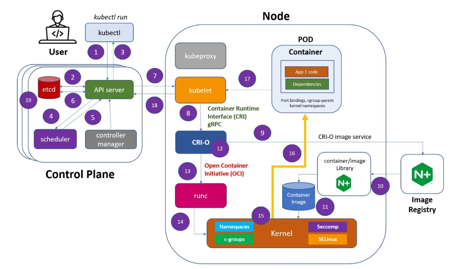
14 – The runc receives the OCI runtime specification and interacts with the Linux Kernel to deploy the container.
15 – The runtime asks Linux for a clone or fork system call. The clone system call is used to create a new process with a specific namespace, and c-groups limit the resources available to the container. In this way, the clone system call plays a critical role in the implementation of containers in Linux, allowing for the creation of isolated and resource-controlled environments for applications and services
16 – Using the Linux Kernel features described before the container is created. This summary does not intend to detail all internal processes in the kernel
17 – As kubelet is a controller that watches for POD changes, it will collect the information that the POD was created
18 – The POD is registered with the API Server by the kubelet.
19 – The POD creation is written in the etcd.
The scheduler checks whether the desired state matches the actual state on subsequent pings.
No other tasks should be performed. The user request is concluded.
It is all for this moment. I hope this information can be helpful; I will come back with more Kubernetes information in the following posts.
Reference links:
https://kubernetes.io/docs/concepts/architecture/cri/
https://kubernetes.io/docs/setup/production-environment/container-runtimes/
https://github.com/opencontainers/runc
https://github.com/containers/crun
https://itnext.io/container-runtime-in-rust-part-0-7af709415cda
https://opensource.com/article/21/8/container-linux-technology


